0
Product is toegevoegd aan uw winkelwagen

Manley Variable Mu

classic vari-Mu compressor voor smooth en buttery compressie.

Prijs op
aanvraag

Voeg dit product toe aan uw offerte

In offerte

Vragen? Betere prijs gezien?

Bel 0512 - 340457 of neem contact op!

Product omschrijving
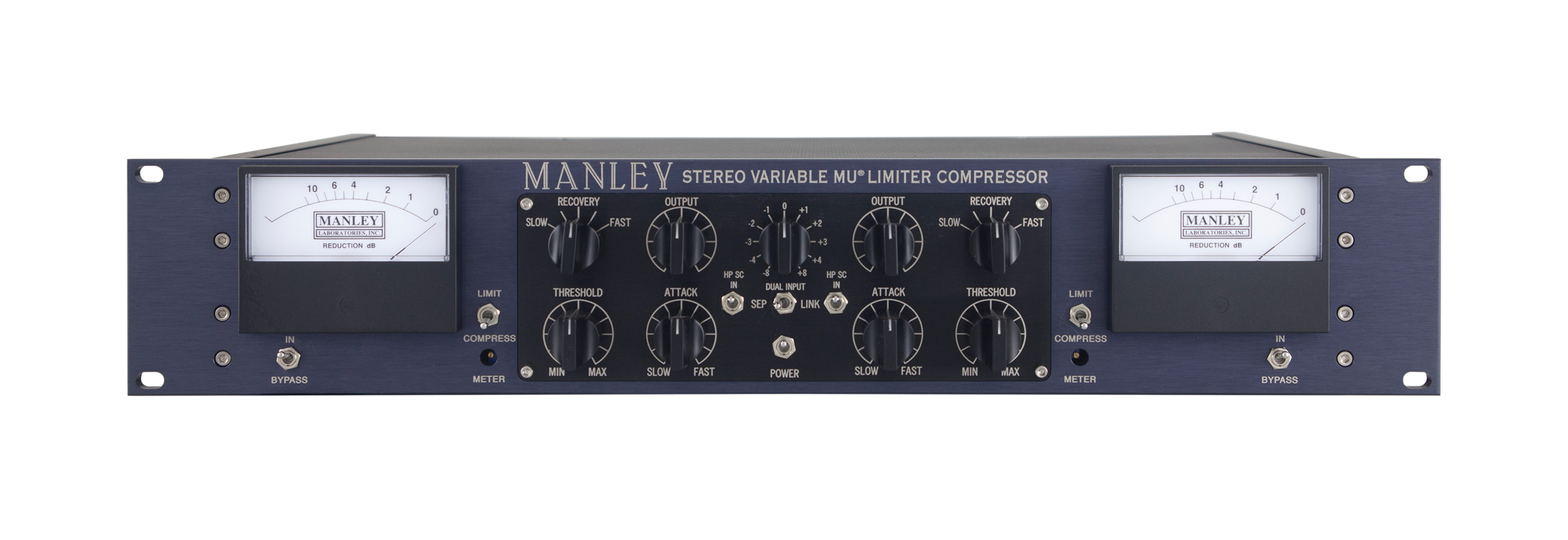
The Variable Mu Limiter Compressor is the GLUE that holds the mix together while crystallizing it into a professional, final product. All-tube, all transformer, an all-American legend. High Pass Side Chain mod now comes standard.

"Excellent design and workmanship. Highest quality sonics. The ultimate 'glue' for a mix."

- Bobby Owsinski, Pro Audio Review, July 1997 -


DETAILS

The MANLEY VARIABLE MU® LIMITER COMPRESSOR has been our best selling product for many years. It is one of the very few compressors that has become a real standard in Mastering studios and contributed to most hit records over the last decade and probably the next. "Mu" is tube-speak for gain, and Variable Mu® is our registered trademark for this limiter compressor. It works by using the "remote cut-off" or re-biasing of a vacuum tube to achieve compression. The precious vintage Fairchild 670 also uses this technique and is one of few all-tube compressor to do so, that we know of. Even the side-chain has glowing rectifier bottles. How’s it work? The unique 5670 dual triode is at the center of the peak-reducing and compression action constantly being re-biased by the vacuum tube rectified side-chain control voltages which cause this tube to smoothly change its gain. Just like that.

The COMPRESS mode is soft-knee 1.5 to 1 ratio while the sharper knee LIMIT mode starts at 4 to 1 and moves to a more dramatic ratio of 20 to 1 when limiting over 12dB. Interestingly, the knee actually softens as more limiting is used. Distortion can be creatively used by turning up the Input and turning down the Output while using very little or no compression. See the gain reduction curves here!

You might notice that the Variable Mu® Limiter Compressor has a ganged input control, but do not jump to conclusions that it is mono-unfriendly. Track away! There are separate threshold and output controls to make compensations with plus you can always adjust your individual source levels elsewhere, right? The advantage of the stereo input control becomes dramatically clear when you switch to LINK mode, and that’s what our Variable Mu® Limiter Compressor does better than anything else: final mix, 2-track, or mastering limiting and compression. Like one reviewer put it: “It’s like pouring a bowl of sweet cream over the mix.” Mmmmmm. Yummy. Give your music a big hug.


SPECIFICATIONS

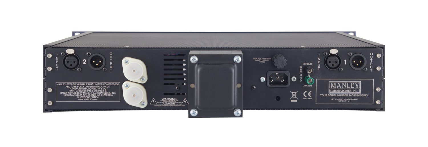
  • MANLEY input & output transformers with nickel laminations in mu-metal cases with flat frequency response from 20Hz-25KHz
  • BALANCED INPUTS & OUTPUTS (600 Ohms)
  • Fully differential ALL-TUBE circuitry
  • Variable Gain vacuum tube: 5670 x2 Standard or 6BA6 x4 T-BAR Mod
  • Amplifying vacuum tubes: 5751 or 12AX7 x2
  • Output vacuum tubes: 12BH7 x2 current production since 4/2016
  •  Output vacuum tubes: prior to MSLC94006 use 7044 or 5687 x2
  • Side Chain Rectifier Diodes: 12AL5 x2
  • Independently regulated B+ and Heater supplies
  • Hardwire BYPASS switch
  • Stepped switch INPUT attenuator as of 10/2011. (older units use Silent dual-ganged potentiometer)
  • RECOVERY 5 steps: 0.2s, 0.4s, 0.6s, 4sec., 8sec.
  • Variable ATTACK: 25msec-70msec
  • Continuously variable THRESHOLD
  • LIMIT (4:1 to 20:1) or COMPRESS (1.5 to 1)
  • HP SC: High Pass Side Chain Filter -3dB @ 100Hz
  • Large ILLUMINATED Sifam METERS (older units before serial number MSLC61642 shipped before 12/2003 use: 26V 1.2W FESTOON LAMPS; Manley's Part Number: VAR016B) Order spare bulbs using our parts order form. (newest units after serial number MSLC61642 shipped after 12/2003 use white LED lighting)
  • STEREO LINK SWITCH - Several units can be linked for Surround (custom order )
  • Maximum gain: 35dB
  • Max. output: +30dBu (26Vrms) 26dB Headroom
  • <0.1% THD @ 1KHz Noise floor: -85dB typical
  • Power Consumption (120/240VAC): 80 watts
  • Unit is factory set for 100V, 120V or 220-240VAC operation for original destination country's mains voltage.
  • Operating Mains Voltage changeable with power transformer changeover switch and fuse value change.
  • Mains Fuse Value for 100~120VAC operation: replace with 1.25A as of 10/2011
  • Mains Fuse Value for 220~240VAC operation: replace with 0.6A (600mA) as of 10/2011
  • Mains Fuse Type: MDA or MDL SLO-BLO Time delay 1 1/4" x 1/4"
  • Mains Voltage Frequency: 50~60Hz
  • Dimensions: 19” x 3 1/2” x 10” (chassis occupies 2u) Power transformer protrudes 3.5" out the back of the chassis.
  • Shipping Weight: 23 lbs.

CUSTOM MODIFICATIONS

HIGH PASS SIDE CHAIN

This modification comes stock on all Manley Variable Mu Limiter Compressors since 12/2009, on both regular and mastering versions.

This mod adds two switches to the front panel, one for each channel, so that when engaged, the side chain will not respond to frequencies lower than 100Hz. (We standardly use 100Hz as the -3dB point. Other frequencies can be custom ordered.) This HP SC Mod can be used with music with heavy bass lines or bass-heavy mixes where you don't want the bass driving the whole action of the compressor.

The filter is a very gentle 6db per octave 1 pole filter, and will typically be down 1-3db at 100 Hz, and down 4-6db at 50Hz. As you decrease the frequency the amount of limiting will decrease also. At the extreme LF (<20Hz) there should be very little gain reduction going on. The whole intent of the filter is to keep very LF stuff (like a heavy kick drum) from activating the compression/limiting so that the overall level doesn't duck with every drumbeat. We can add the High Pass Side Chain option stock boards to older Manley Variable Mu limiters – please contact our Service team for more information.

THE T-BAR MODIFICATION

Backstory: The newer Variable Mu units use 5670 tubes instead of the 6386. By now the availability of the original USA GE 6386 is poor; we don't have any left at all, and what we do have are not usable due to noise, microphonics, bad side-to-side match, etc.

So does the 5670 sound different? Well, up to about 6db of limiting it's about the same. After that point, the 5670 version tends to sound more "squashed" than the original 6386 version. Some like it better, some don't - depends on what you're trying to do.

To solve all these problems, Paul came up with a really good solution: the T-Bar Mod. This uses a pair of 6BA6 pentodes wired as single triodes to replace each dual triode 5670 (or 6386). The 6BA6 T-Bar Mod is the preferred system to use in the Manley Variable Mu® for reasons of ability to perfectly match each phase-halve section and each stereo set, ability to select for lo-noise and lo-microphonic sets for a low cost, and because the action of the 6BA6's so closely resemble the smooth 6386 limiting curves.

We can add the T-bar mod to your Variable Mu unit – contact our Service team for more information, and read more about Paul's special T-bar mod here.

Also of note - both the Manley NU MU’s LIMIT and COMPRESS reduction curves are very, very similar to those in a T-BAR modded Stereo Variable Mu. Check them out in this graphic.

MID/SIDE (a.k.a. Vertical/Lateral, or Sum/Difference)

This modification opens the door to stereo encoding and decoding as well as exciting image enhancement processing capabilities. For instance, setting to compress only the in-phase information allows the augmentation of the stereo image as the out-of-phase content is left untouched. Or, conversely, if you need a "more-mono" mix for broadcast, or vinyl-cutting for instance, you can set it to kill off more of the out-of-phase info which leaves more in-phase material in the final result. Read more about the MS Mod on page 12 of the Owner's Manual. 

In order to add both M-S and the HP SC mods, we move the power switch to the rear panel and install both channels' HP SC switch to the center hole where the power switch was. The M-S switches then flank this switch.


FAQ #1a: When was my unit produced?

Serial Number series codes and production dates: 

MSLC### serials 000-123 1994-1995

MSLC7### serials 124-264 1995-1996

MSLC5### serials 243-576 1996-1997

MSLC6#### serials 577-1699 1997-2004

MSLC8#### serials 1674-3537 2004-2013

MSLC9#### serials 3538-up 2013-present

Note: The serial coding for the mastering versions (MMSSLC) does not include the series digit which follows the "C" as the regular version units MSLC did.


FAQ #2: WHICH TUBES SHOULD I USE IN MY VARIABLE MU® LIMITER COMPRESSOR? 6386? 5670? OR 6BA6 TBAR MOD?

Yes, the newer units use the 5670 tube instead of the 6386. By now the availability of the original USA GE 6386 is poor; we don't have any left at all, and what we do have are not usable due to noise, microphonics, bad side-to-side match, etc.


FAQ #3: DOES THE 5670 SOUND DIFFERENT?

Well, up to about 6db of limiting it's about the same. After that point, the 5670 version tends to sound more "squashed" than the original 6386 version. Some like it better, some don't-- depends on what you're trying to do. To solve all these problems, Paul came up with a really good solution: the T-Bar Mod which uses a pair of 6BA6 pentodes wired as single triodes to replace each dual triode 5670 (or 6386). the 6BA6 TBAR Mod is the preferred system to use in the Manley Variable Mu® for reasons of ability to perfectly match each phase-halve section and each stereo set, ability to select for lo-noise and lo-microphonic sets for a low cost, and because the action of the 6BA6's so closely resemble the smooth 6386 limiting curves.

Read more about Paul's special T-Bar Mod here.

Update 2009: There is a new production 6386 being made by JJ factory. They are very expensive! We have not tested these tubes.

You can read an informative thread about the JJ6386 on Gearslutz to decide if you want to them instead.

Follow the directions below to convert your 5670-powered Manley Variable Mu® to use the 6386 tubes. It's more work to do this than to install our 6BA6 T-Bar mod kits (complete and installed with four 6BA6 tubes selected for quad-perfect matching, lo-noise, and lo-microphonics).

If you want us to convert your unit for you, we can. You'll be supplying the 6386 tubes and we will all pray to the Tube gods that they are quiet and internally matched. Maybe buy extras to be sure. Contact our Service team for more information.

INSTRUCTIONS FOR CONVERTING 5670 TO 6386

Replace 3K57 resistors connected to pins 4 & 6 of 5670 socket with 6K8 1W.

Replace 1K resistors connected to pins 2 and 8 with 511 Ohms.

Replace 10K "balance" trimpot with 500 Ohm trimpot.

Remove 200 Ohm resistor between pins 2 and 8.

Replace 33K 1W resistor between wiper of "GR cal" trimpot and the junction of the meter with 22K 1W (resistor is located near the rear corner of the pcb next to the GR cal trimpot).

Repeat procedure for the other channel; re-calibrate as outlined in the owner’s manual.


FAQ#4 Is it hardwired and bypasses everything from Input to Output or does it still kind of go through the unit in some way, you know, like, through the electronics in the unit at all?

The BYPASS switch is a hardwire BYPASS switch which means it is not going through any circuitry in bypass mode. IN goes straight to OUT.

FAQ #5: WHAT IS THE DIFFERENCE BETWEEN TURNING UP THE INPUT LEVEL CONTROL TO DRIVE THE UNIT INTO LIMITING WITH MORE LEVEL VERSUS USING THE THRESHOLD CONTROL?

The limiting characteristics shouldn't change much, but the distortion characteristics will. The input control on these units is located ahead of the tubes, directly "behind" the input transformer. So as you advance the input control, you're hitting the input tube (which is the gain-varying stage) with more and more signal. Gain reduction is done by making the DC bias on this tube more negative (the threshold control determines how much). The tube has a limit as to how far it can be biased negative to reduce gain before it goes non-linear, and since your audio signal is obviously swinging both positive and negative, the big swings of the audio signal plus the negative gain control voltage will eventually push the tube into the red zone. Tubes like the 6386/6BA6/12BA6 can be pushed a lot farther before the THD builds than tubes like a 5670. Higher signal level also pushes the rest of the tubes and the output transformer harder, which will change the sound character as well.

FAQ #6: I'm really interested to buy the device but it's a big no-go for me that you can't link the output levels. Is there any possibility to get the device with output link or fixed output levels?

Sorry they are individual pots and they are not linked or mechanically ganged. Even if they were on one giant stereo ganged analog potentiometer, you are not guaranteed perfect matching between channels like a computer plugin. Having two individual knobs carries an advantage that you are able to address each channel separately and make fine trim adjustments.

Use two hands, turn both knobs at once. This is what people do with analog gear! Record with your ears!


FAQ #7: WHAT IS the deal with the LINK switch? Everything is shifted over to the one side.

The LINK switch only links the side-chain voltages to encourage similar action of the control voltages. ALL of the front panel knobs remain separate meaning you have to turn each channel’s knobs individually as you normally would when using the unit in dual-mono or separate mode. Set the unit up in dual mono mode, adjust your INPUT, OUTPUT, ATTACK, RELEASE, and THRESHOLD knobs up on both channels, then throw the LINK switch. (Obviously only the INPUT knob is stereo-ganged across both channels. No other controls are electrically or mechanically ganged.)

FAQ #8: My Variable Mu only compresses on one channel unless I put it into link mode. How do I fix this?

Try changing out the rectifier tubes. Swap the bad channel's 12AL5 with the other channel's tube and see if the problem moves to the other side, then you’ll know you have a bad 12AL5 dual diode (or 6AL5 tube on the oldest units.)

FAQ #8a: Everything calibrates fine in separate mode but when switched to link mode, the meters uncal and the level becomes uneven. With signal passing through, its almost like left and right are compressing at different thresholds. Not what is supposed to happen in LINK mode at all!

This is usually indicative of a leaky 5670 input tube or a bad 12AL5 rectifier tube. Head on over to www.tubesrule.com to score some new tubes! Replace both channels and see if that cures this issue for ya.

FAQ #9: After being powered on for around 30 minutes, the right channel of my Variable Mu begins to distort. It sounds sort of like a blown speaker. It doesn't do this when first powered on, but only after the unit is sufficiently warmed up. What gives?

On the older units, a very common failure of this sort can be traced to a bad 5687 output tube. Exchange it with the one from the other channel, give it the 30 minute warmup, and see what happens. If the problem switches to the other channel then it’s time to replace that bad 5687 tube. You can order that from us at www.tubesrule.com

FAQ #10: THIS THING ISN’T WORKING. I JUST BOUGHT IT. FOR THIS AMOUNT OF MONEY, IT NEEDS TO FUNCTION.

OK, listen up: the XLR INPUTS and XLR OUTPUTS are TRANSFORMER-COUPLED so that means you HAVE TO have something connected to all of the pins. 

PIN 1: GROUND
PIN 2: HOT (+) POSITIVE
PIN 3: COLD (-) NEGATIVE

You cannot "float" Pin 3. You can GROUND it if you are driving it from an unbalanced source. But you cannot hook it up to "nothing".

Pay attention when interfacing with some of these interfaces like your Apollo. If you are using TRS - XLR cables, make sure that it is wired:

TRS TIP = HOT (+) to XLR Pin 2
TRS RING = COLD (-) to XLR Pin 3
TRS SLEEVE = GROUND to XLR Pin 1

or 

TS - XLR cable, make sure it is wired:
TS TIP = HOT (+) to XLR Pin 2
TS SLEEVE = GROUND to XLR Pin 1 AND Pin 3

FAQ #11: Hi, I can hear the sound from inside the unit itself, I can compare it to the sound of a cartridge playing a vinyl as your amplifier is turned down. Have you ever noticed that?

Yeah we have! The sound you hear is mechanically coming from the output transformers. Most output transformers in tube guitar amps or hifi amplifiers also do the same thing, but you usually just can't hear them singing because of music coming out of the speakers. This is normal.

FAQ #12: HELP MY FUSE BLEW! Do I need a new transformer?

Probably not. It’s probably the heater rail’s 22uF cap or the RL252 bridge rectifier that failed, specifically, the heater bridge if "TCI" branded is suspect. Disconnect both of these components and then replace the fuse. And apply power back tot he unit. Transformer humming=excess current draw. If the transformer doesn’t blow its fuse and the transformer stops humming, you found the problem. We have an uprated bridge rectifier for older units and we recommend that it be relocated to the the side of the chassis for better heat sinking (as the modern units are).

FAQ #13: OK this is weird. The meter died, the meter light is also out, and there is no sound on that channel. The other channel is fine. What happened?

OK, this is probably a dead 78S12 TO-3 regulator. There are two of them living under their white plastic covers on the rear panel. If the 7812 regulator is bad the heater voltage will not read +6vdc -6vdc on the output pins, but rather something like +1vdc -11vdc referenced to ground. You can source a new 78S12 TO-3 2Amp regulator on the internet or from us.

You can replace the bad regulator yourself if you have a screwdriver. Just make sure to apply more of that white goo to it when you re-mount it to the chassis. The white goo is thermal paste and why the part failed might have been due to that white goo not having been applied evenly? Give it a good schmear to maximize thermal transfer from that part to the rear panel of the chassis. Also, we use a mica washer to electrically isolate the part from the chassis. When you get your replacement regulator, you will want to transfer the mica washer to the new installation. Make sure the thermal paste is layered between the part and the mica washer and the mica washer to the chassis. Line up the pins and the holes carefully as we do not want to electrically short the part to the chassis but we do want to thermally couple the part to the chassis.

Let us know if you can tackle replacing this part yourself, or if you want an RA# to send it in for us to fix for you. If you need our help, fill out the Service Form on this website.

FAQ #14: I'm so sad because I was calibrating the DC balance of the right side of the unit and suddenly the meter went very fast to the left and stop working, and the needle now is bent, the meter is not working, I don't know what happened, could you please help me? 

Normally this happens when adjusting the meter "zero" on the older units that had the adjustment available to you through a hole on the faceplate. Your screwdriver probably slipped, and possibly shorted one of the traces on the circuit board out to the metal faceplate with your metal screwdriver. This is why we tell advise you to use a plastic insulated screwdriver or a “tweaker” adjustment tool. This would have burned out the trimpot, and possibly damaged the meter. You will need to have technician assess this. Everything is repairable, not to worry.

FAQ #15: I have an older Variable Mu with the stereo input pot and one channel is 2dB louder at the 9 o’clock position. How do I calibrate this?

A 1dB imbalance can be heard by your ear, but it isn't the radical imbalance you are describing. A 2db shift with the input control at 9 o'clock will be easily audible. Realize that at the extreme ends of the potentiometer, the matching of the two sections of the input control will be worse. We screen out the badly matched controls at the factory, but typically you're going to see as much as a 1 dB mismatch between the channels in the center of the control's range and worse at the extremes. These units are not digital-perfect for obvious reasons, (high tolerance analog parts) so you're only going to get close with anything, not exact.
Later units (current production) use a stepped input control which is very accurate, but is also costly.

For you, and your older unit, you can easily swing the image back into the center by, first, using the input control more in the center of its rotation, and second, adjusting each channel’s Threshold and Output controls to get the gain reduction equal on both channels and ultimate output from the box equal.

X

Vraag de offerte aan door op bekijk aanvraag te klikken of voeg meer producten toe aan uw aanvraag en klik op 'doorwinkelen'.

Bekijk offerteDoorwinkelen

Het product is toegevoegd aan uw korte verhuur aanvraag. Dit is uw prijs voor 1 week huur of de reeds gekozen periode. Wijzig de huurperiode door op 'bekijk aanvraag' te klikken. Of voeg meer producten toe aan uw aanvraag en klik op 'doorwinkelen'.

Bekijk aanvraagDoorwinkelen

Het product is toegevoegd aan jouw jaarhuur aanvraag. Wijzig de aanvangsdatum door op 'bekijk aanvraag' te klikken of voeg meer producten toe en klik op 'doorwinkelen'

Bekijk aanvraagDoorwinkelen